The Most Important Tool for Prototyping Guitar Pedals: The Beavis Board
How I built myself an incredibly powerful tool for experimenting with different effects pedal circuitry.
What is a Beavis Board?
A beavis board is breadboard attached to a very simple guitar pedal that exposes the guitar input and output, as well as 9V and ground, for easily putting a breadboarded circuit into a guitar effects chain.
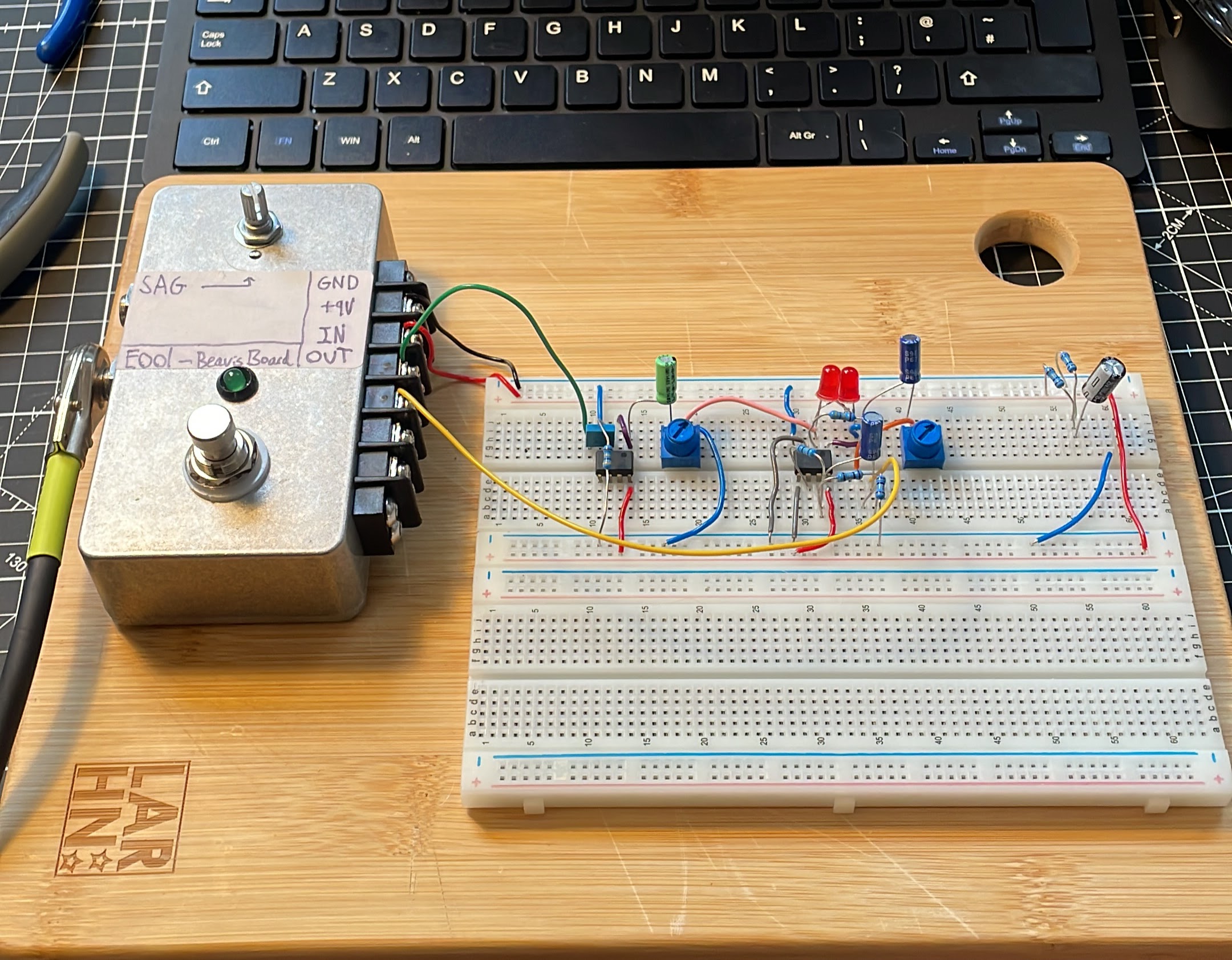
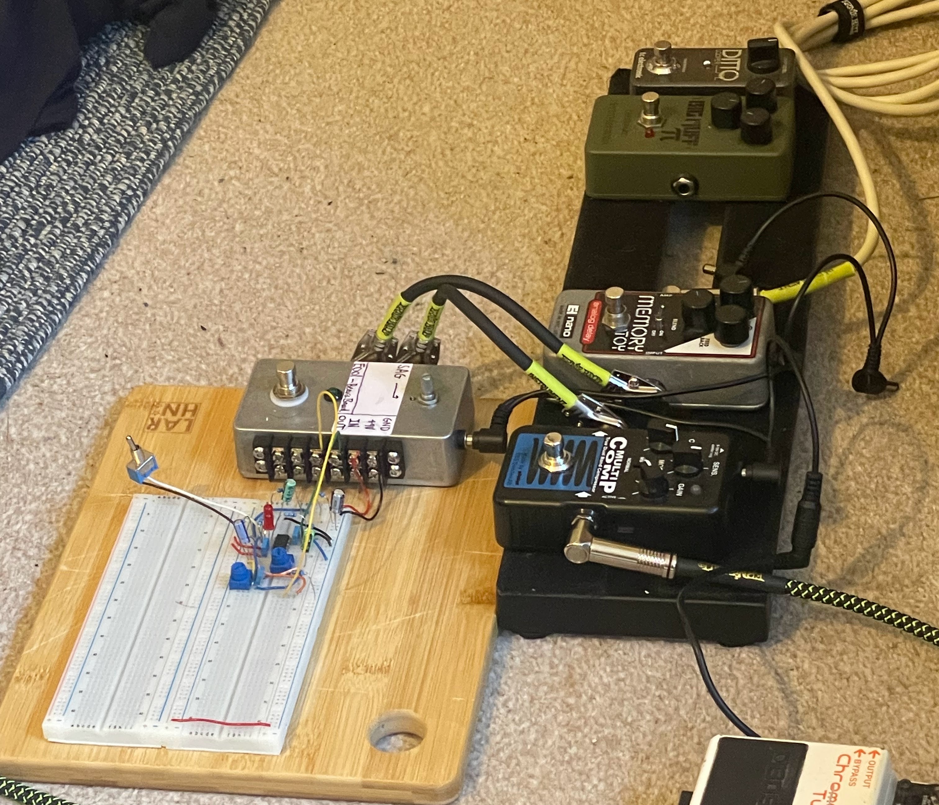
In essence its the parts of the pedal that you will always need to include, assembled neatly already so you don’t have to re-attach every time you start a new breadboard project. In particular the 3PDT latching switch on the stompbox is wired so that the signal fully bypasses the breadboard (ie the hot signal just goes straight from the guitar input to output) in one, which makes it really easy to test the circuit. For example you can put it in series with the rest of your effects, play something, and then switch it on and off to hear the difference.
The reason it’s called a Beavis board is the concept was first popularised by Dano at beavis audio research and was originally sold with a bunch of components as part of a kit. They are no longer in production but are a popular project for DIY guitar pedal hobbyist as they are so useful!
How did I make it?
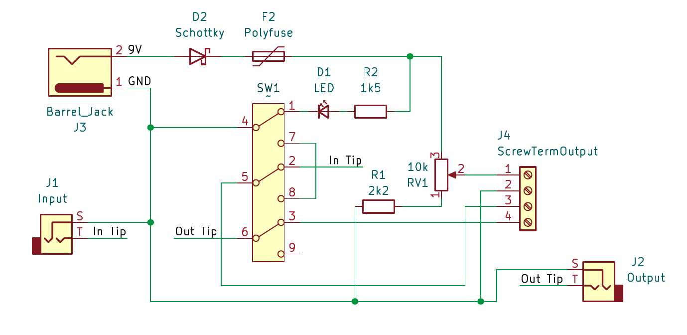
Thankfully there are pretty helpful schematics on the beavis audio research site linked above, but I decided to add a polarity protection diode and a self-resettable fuse for extra safety. This is because I plan on using a 9V “wall-wart” power supply and so because it’s plugged into mains I wanted extra short protection as it was a prototyping board with exposed leads and so the risk felt higher and I didn’t want to blow the power supply. In the end my schematics looked like the following:
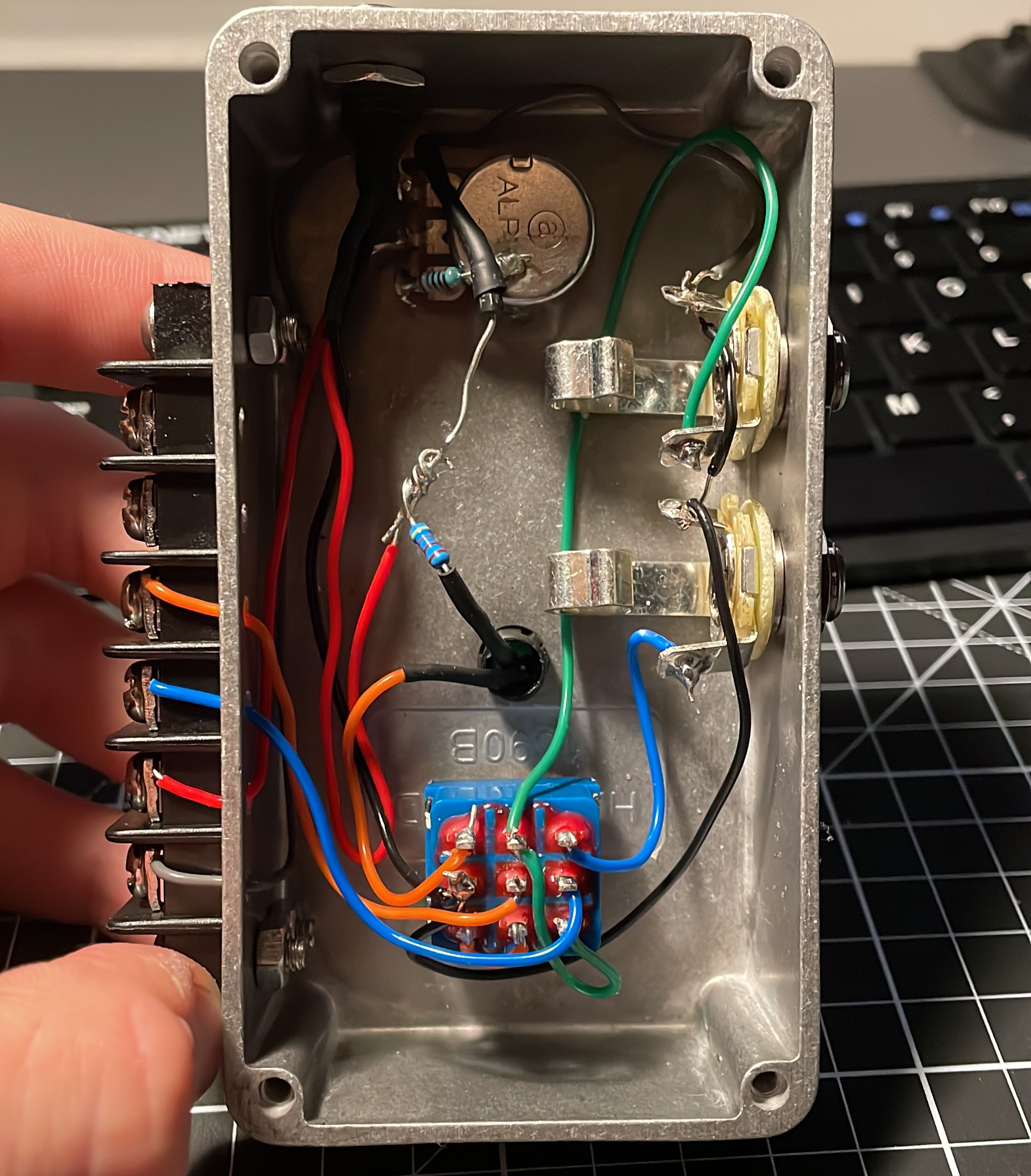
Having designed this, I then set about ordering all the bits from the wonderful BitsBoxUK and then went into my uni Hackspace to drill the enclosure. I ended up using a pillar drill and doing everything very “properly” for the holes but it took so long, I think next time I’ll just use a cordless drill and a cone bit, which I’ve seen online works just as well for the Hammond style aluminium enclosures. I then set about soldering it all together.
The last step was to use double sided tape to attach the stompbox and the breadboards to an old small chopping board. Very pleased with how it all turned out.
Future work
Having devloped my first pedal using the board, I’m keen to extend it somewhat. I think it’d be a really good intro to PCB design to make a simple PCB for attaching a few toggle switches and common potentiometer values to some female headers. Then I could mount that above the breadboards and use some single core wire to attach parts of the breadboard to these switches and pots so I don’t have to faff with trimpots or more hacky ways of toggling parts of a circuit. Could also do some common clipping diode arrangements and maybe even header pins for interacting with a teensy 4.1 board and ADC/DAC for an easy way into DSP development without too much hassle.